Lab 5(a): Obstacle Avoidance
Prelab
Advantages include low cost, and usage of minimum power, whereas, these sensors have low data transfer rate and range of usage is relatively shorter. I would use them in my robot for cases where lighting conditions are not to my favor.Objective
-
The goal of this lab is to enable the robot to perform obstacle avoidance.
Proximity Sensor:
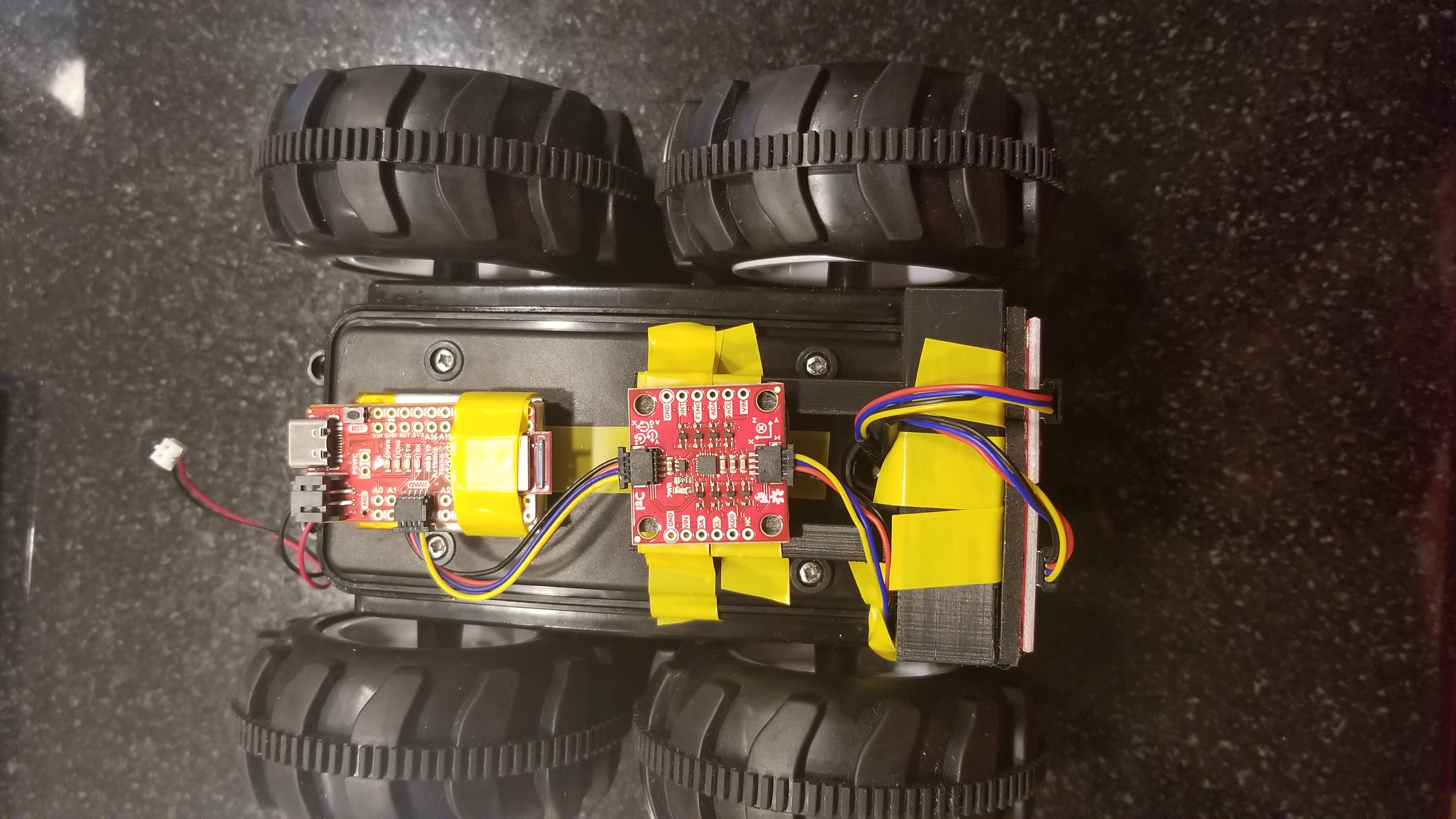
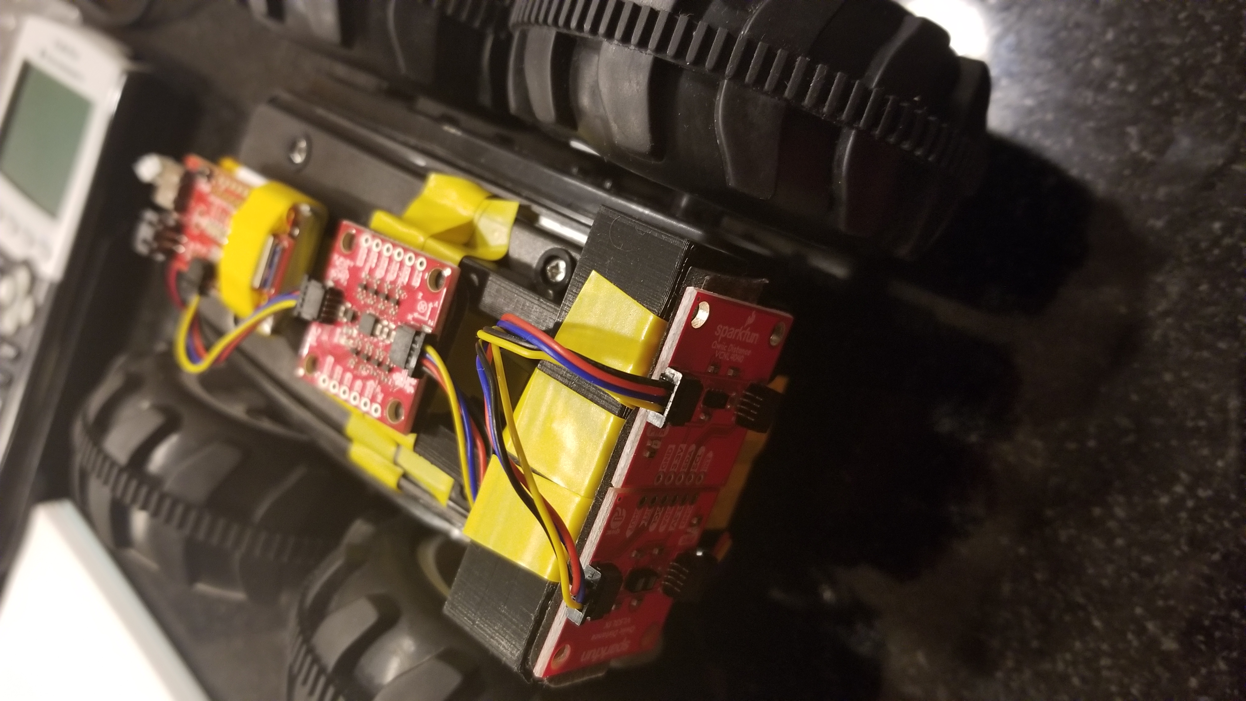
- Installed the SparkFun VCNL4040 Proximity Sensor Library, and hooked up the VCNL4040 to the Artemis board using a QWIIC connector as shown below:
- Ran the code to scan the I2C channel to find the sensor, as shown in datasheet:
-
Test the proximity sensor:
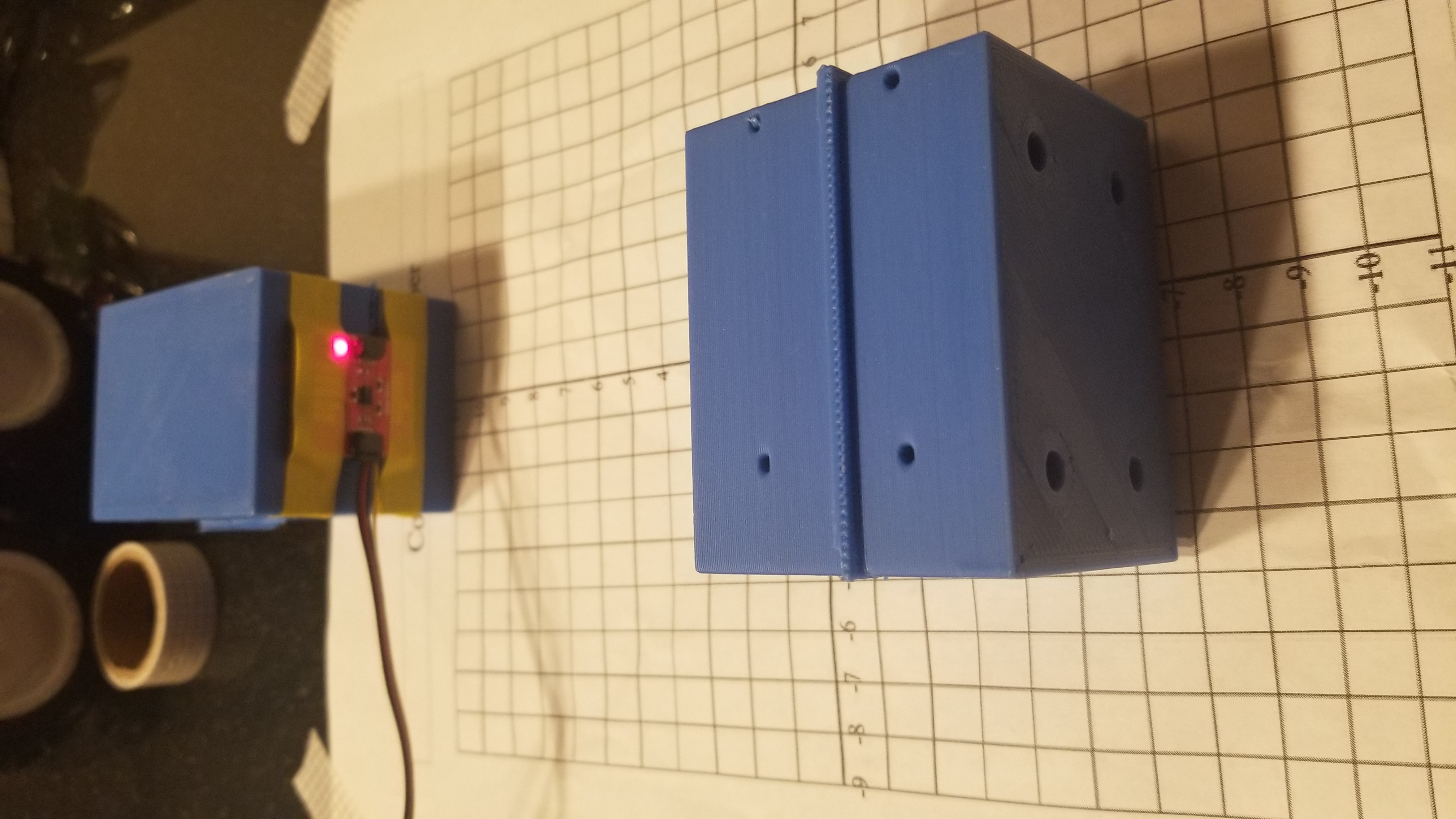
Shown below is the plot of the sensor readings vs the actual distance. The figure shows sensor readings for multiple colors (blue,red,black), and for the color blue it shows two variations, one with bright lighting, and the other with dark lighting. As shown, the sensor is sensitive to the color of the material it is sensing, however, the lighting conditions did not affect the sensor readings considering the difference in the light blue and dark blue curves is very minimal.
Texture:- Black: Plastic (Phone case)
- Blue: PLA (3d printer material)
- Red: Leather (Wallet)
Delay: 4.673 s
Frequency: Every ~67 ms
Time of Flight Sensor:
while (tLowDistanceCount < 20)
{
	while (!distanceSensor.checkForDataReady())
	{
	distanceSensor.startRanging();
	delay(1);
	}
	if (distanceSensor.getDistance() < 100)
	{
	tLowDistanceCount++;
	}
	else
	{
	tLowDistanceCount = 0;
	}
	distanceSensor.stopRanging();
	distanceSensor.clearInterrupt();
}
The timing budget has the following possible values: 15, 20, 33, 50, 100, 200, and 500. The timing budget is the amount of time over which the measurement is taken. The intermeasurement period has to be greater than or equal to the timing budget, therefore, the timing budget can be chosen to be either 15 or 20.
To confirm this, given the speed to be 0.8638 m/s and the Int. period to be 30 ms, the total distance over which a measurement is sampled is 26 mm. If the Int. period were to be higher, then this distance would also be higher which means the robot would not be able to detect an object in time before a collision.
The setup code to test the different settings:
uint16_t budget = 15;
uint16_t period = 500;

distanceSensor.setIntermeasurementPeriod(period);
distanceSensor.setTimingBudgetInMs(budget);
Period/Sampling rate:
-
Long mode: 91.8 ms/ 10.89 Hz
Short mode: ~ 34 ms/ 29.4 Hz
Considering the maximum speed is 0.8638 m/s, the maximum measuring distance for each mode is:
-
Long mode: 79.3 mm
Short mode: 29.4 mm
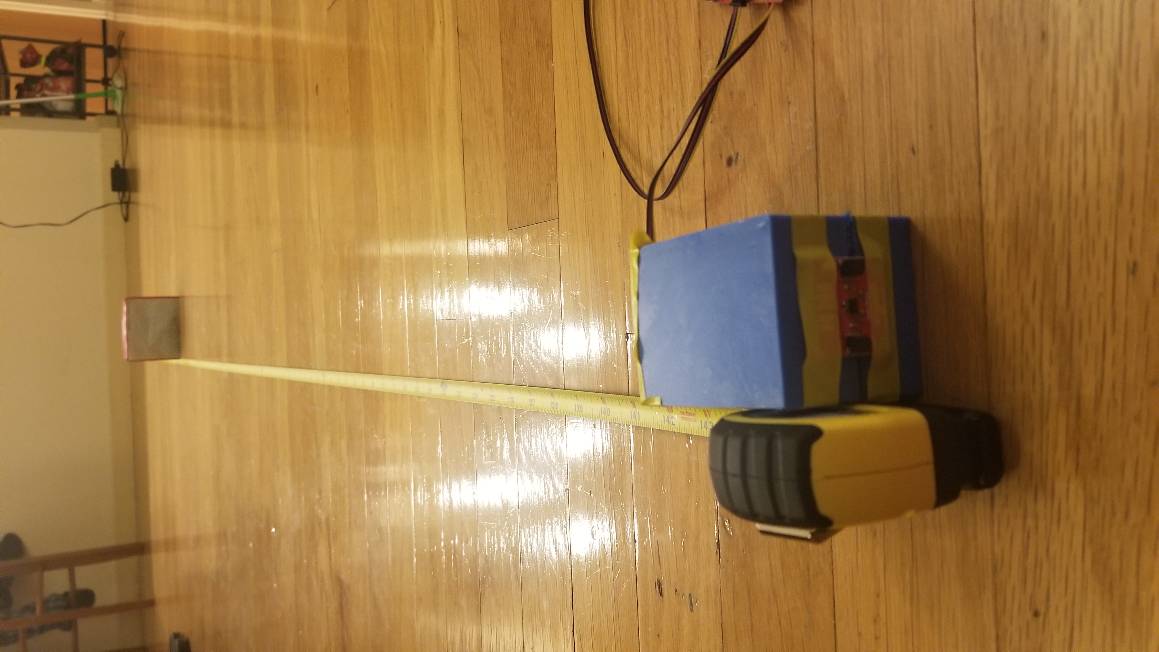
Accuracy at 1.3 meters:
-
Long mode: 1.302 m
Short mode: 1.28 m
Accuracy at 2 meters:
-
Long mode: 1.98 m
Short mode: N/A
Obstacle Avoidance:


// Motors
#include
#include
#include "SCMD.h"
#include "SCMD_config.h" //Contains #defines for common SCMD register names and values
#include "Wire.h"

#define LEDPIN 13

SCMD myMotorDriver; //This creates the main object of one motor driver and connected slaves.

// Distance sensor

#include
#include
#include
#include
#include
#include "SparkFun_VL53L1X.h" //Click here to get the library: http://librarymanager/All#SparkFun_VL53L1X

SFEVL53L1X distanceSensor;


void setup() {
  // ------------------------ Motor Driver ------------------------ //

  Serial.begin(115200);
  pinMode(LEDPIN, OUTPUT);

  //***** Configure the Motor Driver's Settings   *****//
  myMotorDriver.settings.commInterface = I2C_MODE;

  //  set address if I2C configuration selected with the config jumpers
  myMotorDriver.settings.I2CAddress = 0x5D; //config pattern "0101" on board for address 0x5A

  //  set chip select if SPI selected with the config jumpers
  myMotorDriver.settings.chipSelectPin = 10;

  //*****initialize the driver get wait for idle*****//
  while ( myMotorDriver.begin() != 0xA9 ) //Wait until a valid ID word is returned
  {
    delay(500);
  }

  //  Check to make sure the driver is done looking for slaves before beginning
  while ( myMotorDriver.ready() == false );

  //*****Set application settings and enable driver*****//

  while ( myMotorDriver.busy() );
  myMotorDriver.enable();

  // ------------------------ Distance Sensor  ------------------------ //
  Wire.begin();

  if (distanceSensor.begin() != 0) //Begin returns 0 on a good init
  {
    while (1)
      ;
  }

  distanceSensor.setDistanceModeShort();

}

// Motors
#define LEFT_MOTOR 0
#define RIGHT_MOTOR 1
int Rightspeed;
int Leftspeed;
int Speed = 120;
int CloseEnough = 400; // mm

void loop() {


    // ------------------------ Motion ------------------------ //
    // Move forward
    digitalWrite( LEDPIN, LEFT_MOTOR );
    digitalWrite( LEDPIN, RIGHT_MOTOR );
    myMotorDriver.setDrive( LEFT_MOTOR, 0, Speed); //Drive Left wheel forward at Speed
    myMotorDriver.setDrive( RIGHT_MOTOR, 1, Speed); //Drive Right wheel forward at Speed

    // ------------------------ Distance Sensor  ------------------------ //

    distanceSensor.startRanging(); //Write configuration bytes to initiate measurement
    while (!distanceSensor.checkForDataReady())
    {
      delay(1);
    }
    int distance = distanceSensor.getDistance(); //Get the result of the measurement from the sensor


    // If close to obstacle stop
    if (distance < CloseEnough) {

      digitalWrite( LEDPIN, LEFT_MOTOR );
      digitalWrite( LEDPIN, RIGHT_MOTOR );

      // Stop Robot
      myMotorDriver.setDrive( LEFT_MOTOR, 1, 0); // Stop Left
      myMotorDriver.setDrive( RIGHT_MOTOR, 1, 0); // Stop Right
      delay(200);

      // Move backwards and curve Counter clockwise
      Rightspeed = Speed;  Leftspeed = 3*Speed/2;
      myMotorDriver.setDrive( LEFT_MOTOR, 1, Leftspeed);
      myMotorDriver.setDrive( RIGHT_MOTOR, 0, Rightspeed);
      delay(250);

      // Stop Robot
      myMotorDriver.setDrive( LEFT_MOTOR, 1, 0); // Stop Left
      myMotorDriver.setDrive( RIGHT_MOTOR, 1, 0); // Stop Right
      delay(200);

      // Rotate Counter clockwise
      myMotorDriver.setDrive( LEFT_MOTOR, 1, Speed); // Left goes backwards
      myMotorDriver.setDrive( RIGHT_MOTOR, 1, Speed); // Right goes forwards
      delay(3000);

      // Stop Robot
      myMotorDriver.setDrive( LEFT_MOTOR, 1, 0); // Stop Left
      myMotorDriver.setDrive( RIGHT_MOTOR, 1, 0); // Stop Right
      delay(200);

    }

    Serial.print("Distance(mm): ");
    Serial.println(distance);
    distanceSensor.clearInterrupt();
    distanceSensor.stopRanging();


}
Lab 5(b): Obstacle Avoidance on the virtual robot
Simulation:
Code:
- The duration of a velocity command is 0.5 as shown in the code above.
- The robot curves backwards in a counter-clock direction, and then rotates for another 0.5 seconds at 0.2 angular velocity. Therefore, in total it rotates by 0.7 radians in the counter-clock direction.
- The virtual robot managed to sense the distance at a linear speed of 0.5. If the velocity was any higher, the robot would fail to sense the wall in time to avoid it.
- The closest the virtual robot can get to the walls (obstacles) is about 0.3. This is because of the thickness of the robot itself. As shown in the video, the robot gets very close to the wall sometimes. The threshold picked to check with the sensors is 0.75, to ensure this collision does not take place.
- After running it multiple times, there has not been an instance where it has not worked. However, I suspect that the robot may crash when an edge is placed in front of it such that the depth is much higher since it cannot measure the depth to the edge itself. The robot got close but never collided.
def perform_obstacle_avoidance(robot):
while True:
	# Obstacle avoidance code goes here

	# Move forward
	robot.set_vel(0.5,0)

	# If close to obstacle
	if robot.get_laser_data() < 0.75:

		# Stop Robot
		robot.set_vel(0,0)

		# Move backward and rotate
		robot.set_vel(-0.3,0.5)
		time.sleep(0.5)

		# Turn 90 degrees
		robot.set_vel(0,0.2)
		time.sleep(0.5)


perform_obstacle_avoidance(robot)

