Lab 4(a): Open Loop Control (Real Robot)
Objective
-
The goal of this lab is to change the remote control capabilities into an open loop control system
within the car.
Note: Code for Part A can be found here
Steps for Part A:
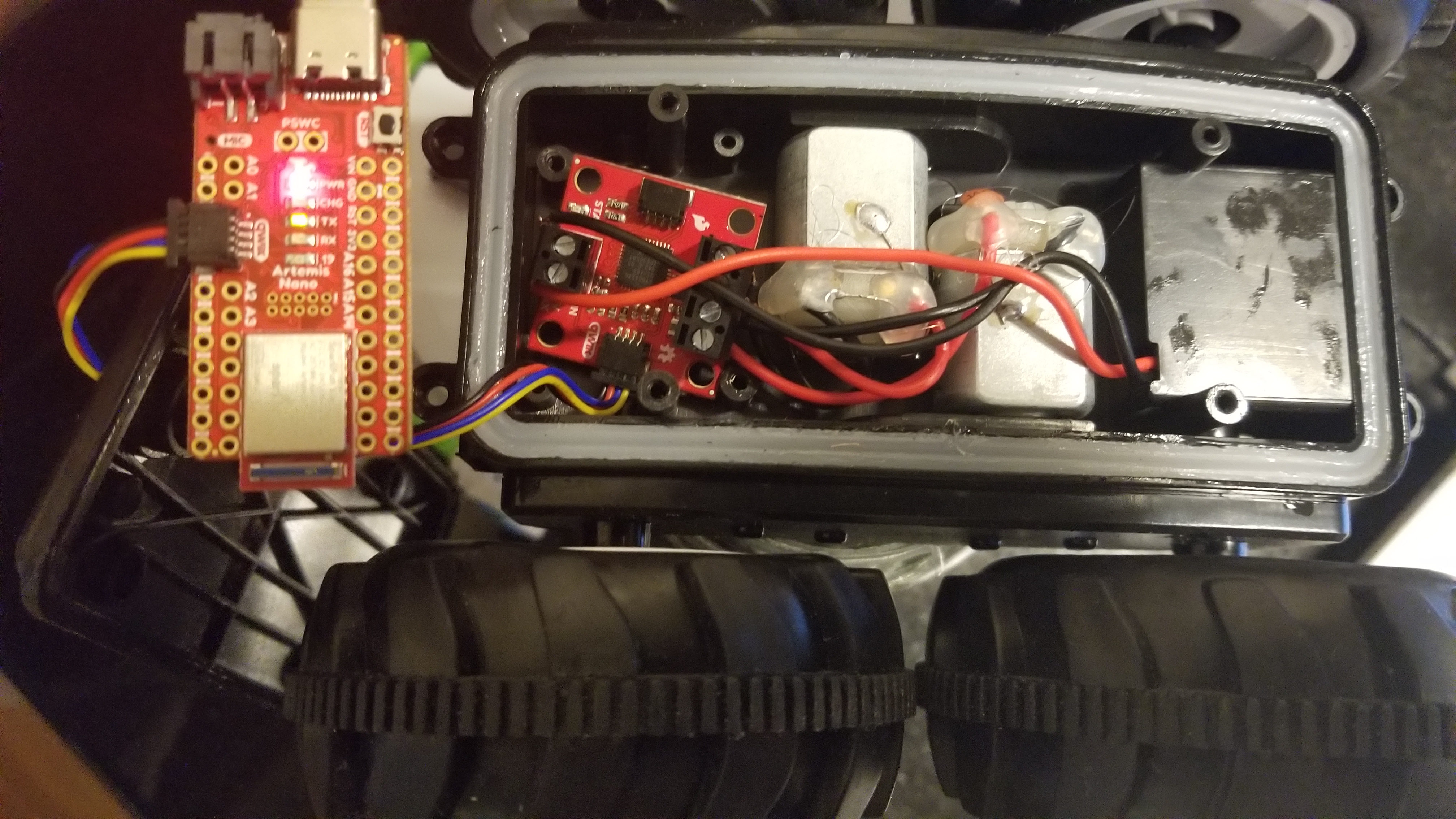
- Hooked up the Artemis and the motor driver using the Qwiic connector:
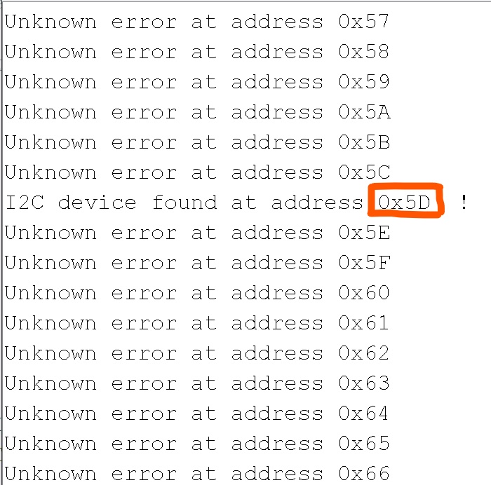
- Ran the code to find the address of the SCMD and it matches the one reported on Sparkfun:
-
Took the car apart as shown in the figure in Part 1. Removed the shell and bumpers from the car,
removed the battery, and took out the PCB. Finally, cut the motor wires and power wires and
hooked them onto the SCMD. I faced two problems while doing this:
- Screwing in the wires without a wire stripper and not enough length on the motor wires was difficult.
- I stored the motor driver in place of the PCB, and made the hole (where the power button used to be) bigger to fit the Quiic wire through and to the Artemis board as shown in Figure 1.
-
-
Used the Arduino IDE and installed the SCMD library.
-
In order to check if I can control both motors, I used the example "Motor Test" and made
one small change shown below. I updated the address to the correct address of the SCMD
obtained in Part 2:
As shown below, both the motors work after making this change:
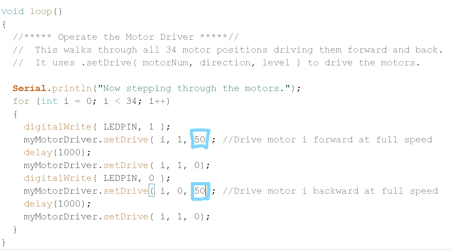
- While exploring the lower limit for which each of the motors still turns, I noticed that the lower limit varies as I alter the value up and down. As shown below, I altered the third parameter in the "myMotorDriver.setDrive". We already know the upper limit is 255, and after experimenting a lot, the lower limit resulted to be 50. The value of the lower bound kept fluctuating as I performed the test but it seemed to alter around the value 50.
-
After running the robot without any factors, the robot started drifting to the left.
This may be due to a number of reasons, friction due to the wheels or internal
resistances within the motor, etc. So to solve this issue, I considered four cases:
- Case 1: Robot's input speed is the lower limit 50.
- Case 2: Robot's input speed is the upper limit 255.
- Case 3: Robot's input speed is between the lower limit and the mid point between lower and upper limits.
- Case 4: Robot's input speed is between the Upper limit and the mid point between lower and upper limits.
- 0 < Cf < 0.5: Robot will lean left (where 0 is when it turns left the most)
- 0.5 < Cf < 1: Robot will lean Right (where 1 is when it turns right the most)
-
In order to check if I can control both motors, I used the example "Motor Test" and made
one small change shown below. I updated the address to the correct address of the SCMD
obtained in Part 2:
As shown below, both the motors work after making this change:
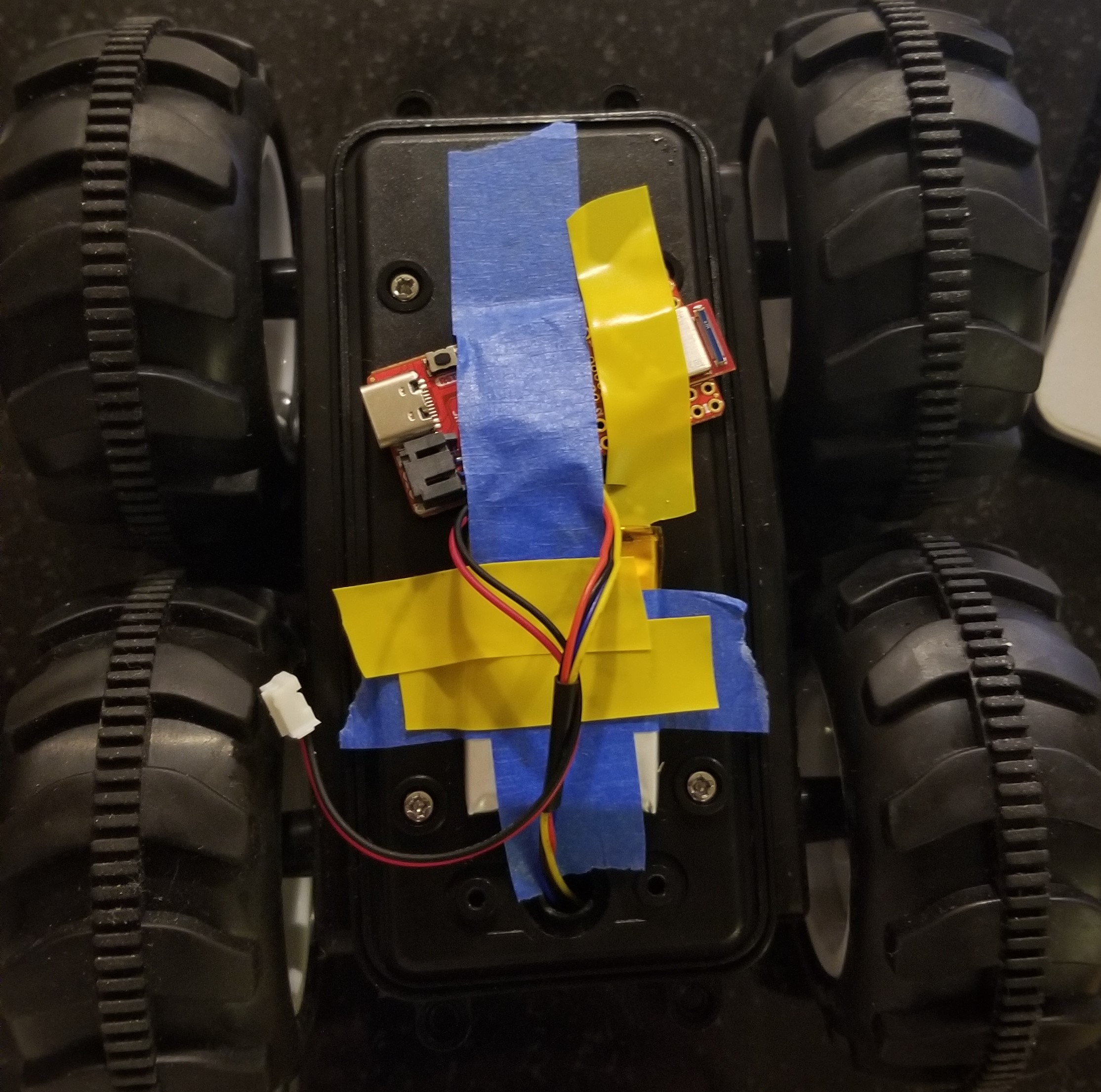
- Assembled the robot completely. Closed the battery pack and the motor driver within the robot. Due to a lack of space the artemis board and the Lipo battery were taped onto the bottom side of the robot as shown below:
-
To demonstrate the open loop and untethered control of the robot, I decided to use concepts from
Lab 2 where
we used the PDM to determine the frequency in the surroundings of the robot. I combined the code
from Part 4
- Driving the robot straight, and the code from example PDM/Microphone output. I chose a
threshold of the
frequency to be 2000:
- If the frequency is above this threshold, it starts acting crazy (rotating at full speed).
- If the frequency is below this threshold, then it moves slowly in one direction.
Lab 4(b): Open Loop Control (Virtual robot)
Objective
-
The goal is to familiarize myself with the simulator and the virtual robot, and Jupyter.
Perform tests on the virtual robot
-
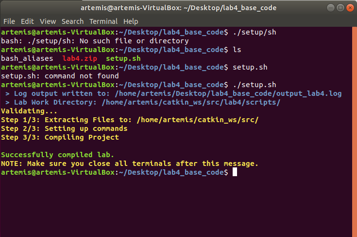
Successful setup process after running the setup.sh:
-
Range finder activated as shown below:
-
Got the Robot's pose as shown below:
-
Moved the robot as instructed in Jupyter:
-
Created a rectangular trajectory by using an open loop control on the robot:
Code
# Repeat 4 times
for x in range(1,5):

	# Move forward and stop
	robot.set_vel(v=0.2,w=0.)
	time.sleep(4)
	robot.set_vel(v=0,w=0)

	# Turn Left
	robot.set_vel(v=0,w=-0.4)
	time.sleep(3.9)
	robot.set_vel(v=0,w=0)
